ニクシー時計:電源
Back in October of 2006 (my senior year of high school), I started designing a nixie tube clock. I was reading Nuts and Volts at the time and was inspired by two back-to-back issues that detailed building a high-voltage microprocessor controlled power supply and a nixie tube clock. If you haven't already, please read the introduction.
The nixie tube was invented in 1951 by a vacuum tube manufacturer called Haydu Brothers Laboratories. The tube consists of ten stacked cathodes in the shape of the Arabic numerals 0 through 9 surrounded by an anode mesh. The whole thing is enclosed in a neon-filled glass envelope. By applying a bias to the anode of around 170 volts, the individual cathodes can be illuminated by grounding one cathode at a time. The grounded cathode will light up with a nice warm orange glow. It's really a beautiful effect.
The trick with these old tubes, though, is driving them with modern electronics. Back in their heyday, electronic devices had a multitude of voltages running through them, ranging from low (12 volts or so) to rather high (300 volts or more). Generating a few mA of bias voltage for a few nixie tubes was not complicated. These days, most everything after the wall wart or power supply is no higher than 12 volts. And I don't feel particularly fond of messing with line voltages. Assuming I will power the clock off of a 12 volt wall wart, the question becomes; how does one convert 12 volts DC to 170 volts DC? When I started thinking about the project, I had no clue how to go about doing this. I could certainly make a voltage a lot smaller (voltage divider, linear regulator, etc.), but how does one go about making it bigger? Before I really started thinking about how I would build the whole clock, I knew I had to have a working power supply. And the issue of nuts and volts that had come in the month before had the perfect solution – how to convert 5 volts DC to upwards of 200 volts DC.
The article detailed construction of a boost style DC to DC converter. These converters use two switches and an inductor to move energy from a lower potential to a higher potential. They are not isolated (both the input and the output share the same ground) and they do not invert the output voltage. The boost converter's inductor is connected between the input and one side of both switches. One switch is connected to ground and the other to the output. The switch connected to ground is controlled by the boost controller while the other one is generally a diode. The circuit works by dumping current through the inductor to build up a magnetic field by closing the first switch. When the switch is opened, the magnetic field starts to collapse and it induces a current in the inductor. However, the current can't flow to ground through the first switch, so it is forced to go to a higher potential through the diode. Less current flows than was originally let through the inductor, but the current that does flow is at a proportionally higher voltage. Assuming the switches and inductor are ideal, the input power will equal the output power. The saturation current of the inductor places an absolute limit on the amount of power that can be passed through the converter at a constant input voltage while the inductance determines the frequency at which the converter operates. More inductance means it takes longer for the current to build up to saturation and therefore a lower operating frequency. Varying the duty cycle of the controlled switch (percent of period in which the switch is turned on) will control the amount of power passed through the converter, necessitating the use of a feedback control circuit that tries to keep the output voltage fixed at a certain point by adjusting the duty cycle.
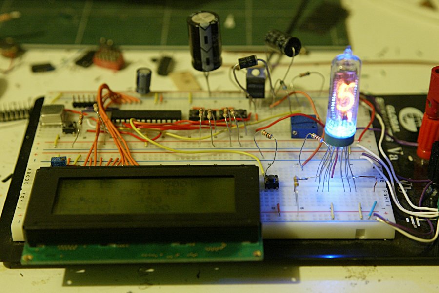
Following the schematic in the article, I built the power supply. I ran it off of a 5v benchtop power supply. I hooked up an LCD and a couple of buttons for debugging. Then I started working on the firmware. It wasn't terribly complicated, but it took quite a bit of trial and error. I used one of the MOSFET transistors I had purchased some time ago for another project since I had a whole tube of them. I experimented with several different inductors that I had lying around. Eventually, I got it to output voltages higher than 5 volts. Unfortunately, I quickly figured out that the biggest voltage it would give me was 50 volts. I could not get it to go any higher. I tried making the test a bit more realistic. Since I would run be running the clock on a 12 volt wall wart, I switched over to a 12 volt power supply and I added a 7805 linear regulator. However, I still had no luck getting the output to go higher than 50 volts.
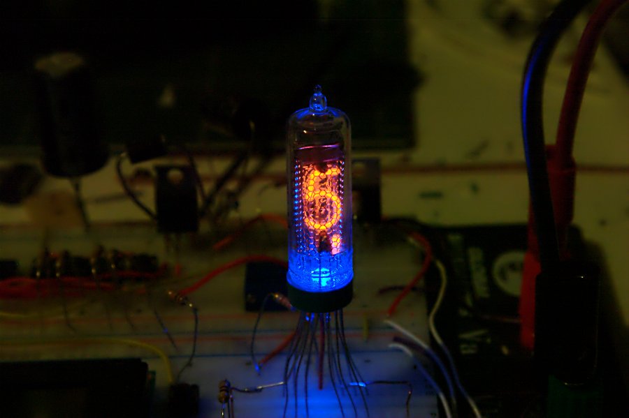
Then I had a stroke of genius. Maybe I could get the power supply to work more efficiently if I used a higher input voltage. After all, why step 12 volts down to 5 then back up to 200? There's really no point in doing that; it's quite inefficient. So I rearranged the circuit a bit so the input of the boost converter was connected to the 12 volt input. Still no luck. In desperation, I started looking at datasheets for the various parts. I started with the MOSFET. BUZ11, N-Channel power MOSFET. Id is 30 amps. Vds is 50V. Vgs is–hey, wait a sec–Vds is 50V? D'oh! Perhaps I need another MOSFET. One short trip to Fry's later I had a 400V MOSFET, a 400V diode, and a 250 volt capacitor. After swapping out the parts, I ramped up the voltage again. 20 volts, 40 volts, 50 volts, 60 volts (oh yeah, solved that problem), 80 volts, 100 volts, 120 volts (getting a little nervous now…), 140 volts, 170 volts. It worked!!! I turned off the supply and hooked up one tube and added a blue LED underneath. Then I ramped up the voltage again. As it passed around 140 volts or so, I started to see a dull red-orange glow in the tube. Once it reached 170 volts, the tube was very nicely lit. Power supply works!
The next step in driving the tube is the tube switching. Four tubes means 4 anodes to control and 48 cathodes (each tube has 12 cathodes, 10 numerals plus 2 dots at the bottom left and right). One method is to connect all 4 anodes to power and switch all the cathodes. However, 48 transistors is a bit much. I'm going for compact here, remember? Also, the microcontroller I'm using has only 28 pins. And if I do a two-board design for compactness, I want to minimize the interconnections between the two boards. More wires = more work. And more wires take up more space. One method to knock out transistors and control lines at the same time is to use 4 to 10 line decoder chips for the digits. It just so happens that there is a very special chip called a 74141 that was designed specifically to drive the cathodes of nixie tubes. The output pins are high-voltage, open-drain transistors. Perfect. Only one problem, they stopped making them in the 80s, so they're impossible to find. Fortunately, I managed to get my hands on the Russian pin-equivalent part, the K155ID1. And since I naturally want to use as few of these hard-to-find chips as possible, I also opted to switch the anodes of the tubes as well. That means 2 transistors per tube to switch the anode plus one decoder and two transistors to switch the cathodes. One decoder and 10 transistors, much more efficient than 48 transistors. Also, it only takes 12 control lines to control a 6 tube display and controlling a 4 tube display involves simply ignoring 2 of those. Future expandability! Also, connecting the LED anodes to the control lines and adding one more transistor for the LED cathodes allows control of the LEDs under the tubes with only one more IO pin. This sets the minimum number of interconnect lines at 16 – 6 tube select lines, 4 binary digit select lines, 2 decimal point control lines, 1 led control line, ground, 5 volt logic supply, and high voltage tube bias. Perfect!

