This is an old revision of the document!
Nixie Clock: History
In my senior year of high school, the October 2006 issue of Nuts and Volts featured an article about a Nixie tube clock. The previous issue had discussed a high voltage power supply built around a PIC microcontroller. I had been experimenting with PIC microcontrollers for quite some time before and I was intrigued by the prospect of using a PIC microcontroller to generate a rather high voltage from a logic-level supply. I didn't have much use for it, though. After seeing the Nixie clock article, I now had the perfect application for it. So, I bought several tubes off of ebay, direct from the Ukraine, and got to work.
The most important part of the clock is the nixie tube. I wanted to make a clock with a low part count and a small physical size, so I settled on a four tube clock. I did some research online to determine the most optimal drive configuration for the least complexity hardware-wise. Many designs biased the anodes directly and then used either ten transistors and a demultiplexer chip or a special high-voltage demux chip per tube. I definitely liked the hv demux chip idea because it means I need one part instead of 21 (demux + 10 transistors + 10 bias resistors). Another site that I looked at added anode-side switching and then used only one driver chip. I really liked this idea, primarily because the driver chips are expensive and, just like the tubes, I had to order them directly from the Ukraine. Replacing three driver chips with eight transistors and eight bias resistors seemed like a fair trade.
Then I had to figure out how to do the other thing the clock will have to do well – keep track of time. I settled on a Maxim/Dallas part, the DS1340C, with an I²C interface and a built-in crystal, further reducing the parts count.
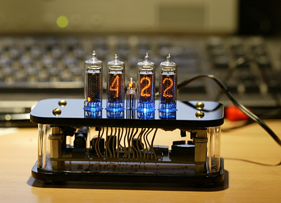
In researching how I would build my clock, I looked at many pictures online of other clocks. Some were completely over-the-top, some were too simple. I wanted a sleek, modern looking clock that isn't too difficult to build. One of the ideas I liked about one of the completely over-the-top clocks is blue lights underneath the tubes. The little hole in the bottom of the spacer on the bottom of the tubes that I bought happens to be just the right size for a 3mm LED. So I bought a bunch of 3mm blue LEDs off of ebay.
For the case, I decided on a simple design based on acrylic. The top and bottom would be black acrylic and the sides would be made of clear acrylic.
I decided to write the firmware for the clock in C in mikroElektronika's mikroC development environment; I had bought it along with an EasyPIC4 development board from them some time before.
The result of a pile of work spread out over several months is shown above.